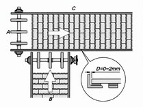
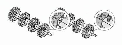
Arrangement
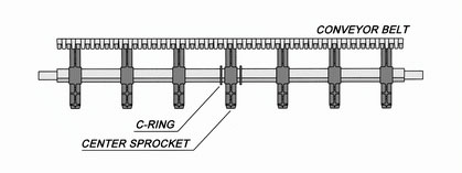
The center sprocket must be set in the middle position of the conveyor belts width, for making sure the transporting direction will keep the aligned movement during conveyor running. The drive / Idle sprockets have to be fixed by C shape retain rings on both side, to assure sprockets are locked on the right position. These retain sprockets will provide the positive track to keep the belt running properly between side frames of the conveyor.
Except for the center sprocket must be set in the middle position of the shaft, the other sprockets are not necessary to be fixed; they are allowed to be free to engage with the belt in the situation of thermal expansion and contraction.This drive method can prevent the wrong engagement of belt and sprockets.
Regarding to the spacing arrangement between sprockets, please refer to Sprocket Spacing in left menu.
Sprocket Arrangement of Turning Conveyor Belt
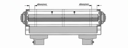
While arranging sprockets, the spacing will be no more than 145mm and the center sprocket has to be fixed by retainer rings.
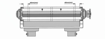
When the length of a conveyor system is less than 4 times the width of belt, the spacing is no more than 90mm. The spacing between the outside sprocket and belt edge must be more than 45mm.
Regarding to the spacing arrangement between sprockets, please refer to Sprocket Spacing in left menu.
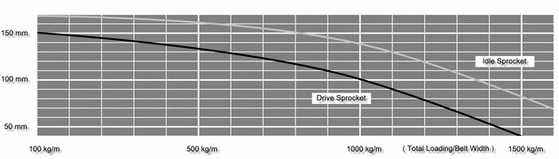
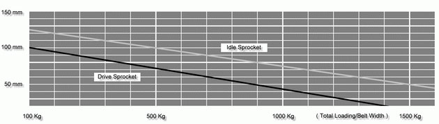
Sprocket Spacing Diagram of Series 100
Notes
The graph above is the spacing data of sprocket center; these data are approximations and for reference only. Please prioritize the actual position that sprockets engage with belt while designing and processing.
Please refer to the curve data and set the spacing while installing sprockets. It must be allotted averagely and smaller than the curve data.
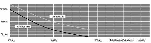
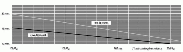
Sprocket Spacing Diagram of Series 200
Notes
The graph above is the spacing data of sprocket center; these data are approximations and for reference only. Please prioritize the actual position that sprockets engage with belt while designing and processing.
Please refer to the curve data and set the spacing while installing sprockets. It must be allotted averagely and smaller than the curve data.
Sprocket Spacing Diagram of Series 300
Notes
The graph above is the spacing data of sprocket center; these data are approximations and for reference only. Please prioritize the actual position that sprockets engage with belt while designing and processing.
Please refer to the curve data and set the spacing while installing sprockets. It must be allotted averagely and smaller than the curve data.
Sprocket Spacing Diagram of Series 400

Notes
The graph above is the spacing data of sprocket center; these data are approximations and for reference only. Please prioritize the actual position that sprockets engage with belt while designing and processing.
Please refer to the curve data and set the spacing while installing sprockets. It must be allotted averagely and smaller than the curve data.
Sprocket Spacing Diagram of Series 500
Notes
The graph above is the spacing data of sprocket center; these data are approximations and for reference only. Please prioritize the actual position that sprockets engage with belt while designing and processing.
Please refer to the curve data and set the spacing while installing sprockets. It must be allotted averagely and smaller than the curve data.
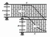
cross & parallel
During the application of conveyor belts for cross connection, special care must be taken for the fixed method of sprockets .
When conveyor B intersects with conveyor A, the sprocket of conveyor A that is close to conveyor B must be fixed. Besides, the value D of conveyor A (Table 9 ) must be reduce, and the spacing must be added to the value D of side C. All the expansion tolerances of conveyor A are kept in side C to get the best effect of connection.
Sprocket Arrangement for Parallel Connection of Conveyors
During the application of conveyor belts for parallel connection, special care must be taken for fixing the drive sprocket of both conveyors on the side that is close to another conveyor. For the value D, please refer to the illustration that was mentioned above, and reserve the spacing of expansion tolerance in side C to let the spacing between the frames of two conveyors reduce to the lowest limit when temperature changes.
Idle Sprocket
The center sprocket of idle shaft should be fixed by retain rings, to make sure the transporting direction will be straightforward without slanting. The number of drive sprockets minus 2 is the number of idle sprockets. The spacing has to be distributed averagely on the shaft. The quantity of idle sprockets is not able to less than 3 pieces . Please refer to Sprocket Spacing in left menu.
Idle Sprocket Arrangement for Turning Conveyor Belt
The spacing of the sprocket on idle shaft will be no more than 150mm during design. If the conveyor system is designed in bidirectional conveyance, the arrangement of idle sprockets should be the same as the drive sprockets. Please refer to Sprocket Spacing in left menu.
Intermittent Operation
While the conveyor is in the situation of intermittent operation, it will easy to occur the phenomenon of belt shifting on both sides and cause a improper engagement between the belt and sprockets. The free sprockets will shift toward both sides of the shaft because of they are not fixed by retainer rings. If the condition does not be adjusted, it will influence the operation of the conveyor.
Hexagonal Adapter
For light product loading conveyance, the drive/idle shaft can adopt the round bore adapter to instead of the processing of square shaft . It is recommended for applying to the working environment of light loading and the belt which width is within 450mm.
Retainer Rings
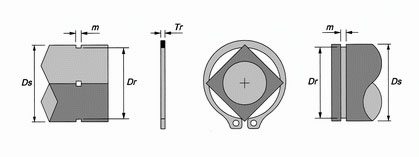
| DS | Code | m | Tr | Dr | |
|
Square |
38 mm | 52 | 2.2 mm | 2 mm | 47.8 mm |
| 50 mm | 68 | 2.7 mm | 5 mm | 63.5 mm | |
| 64 mm | 90 | 3.2 mm | 3 mm | 84.5 mm | |
|
Round |
?30 mm | 30 | 1.8 mm | 1.6 mm | 27.9 mm |
| ?45 mm | 45 | 2.0 mm | 1.8 mm | 41.5 mm | |