Horizontal Conveyor
In the meat settling factory, the ambient temperature is controlled in 21°C, and adopted HS-100 for meat settling line. The average weight of the meat is 60kg/M2. The width of the belt is 600mm, and the total length of the conveyor is 30M in horizontal design. The conveyor belt operating speed is 18M/min in the humidity and cold environment. The conveyor starts in unloading and no accumulating condition. It adopts sprockets with 8 teeth in 192mm diameter, and the 38mm x 38mm stainless steel drive shaft. The relevant calculation formula are as follows.
Calculation of unit theory tension - TB
|
FORMULA : |
TB =〔 ( WP + 2 WB ) × FBW + Wf 〕× L + ( WP × H ) |
| TB =〔 ( 60 + ( 2 × 8.6 ) × 0.12 〕× 30 = 278 ( kg / M ) | |
| Because of it is not a piling up conveyance, Wf can be ignored. |
Calculation of unit total tension - TW
|
FORMULA : |
TW = TB × FA |
| TW = 278 × 1.0 = 278 ( Kg / M ) |
Calculation of unit allowable tension - TA
| FORMULA : | TA = BS × FS × FT |
| TA = 1445 × 1.0 × 0.95 = 1372.75 ( Kg / M ) | |
| Because of TA value is larger than TW, Therefore, to adopt with HS-100 is proper selection. |
Please refer to Sprocket spacing of HS-100 in Drive Sprockets Chapter; the maximum sprocket spacing is approximately 140mm for this design. Both drive/Idler end of conveyor should be placed with 3 sprockets.
-
Deflection ratio of drive shaft - DS
| FORMULA : | SL = ( TW + SW ) × BW |
| SL = ( 278 + 11.48 ) × 0.6 = 173.7 ( Kg ) | |
| In comparison with the Maximum Torque Factor in Shaft Selection unit, we know that the use of 38mm × 38mm square shaft is safe and proper selection. | |
| FORMULA : | DS = 5 × 10⁻⁴ × ( SL x SB3 / E x I ) |
| DS = 5 × 10⁻⁴ × [ (173.7 × 7003 ) / ( 19700 × 174817 ) ] = 0.0086 | |
| If the calculation result is smaller than the standard value that listed in the Deflection Table; adopting two ball bearings is enough for the system. |
-
Calculation of shaft torque - TS
|
FORMULA : |
TS = TW × BW × R |
| TS = 10675 ( kg - mm ) | |
| In comparison with the Maximum Torque Factor in Shaft Selection unit, we know that the use of 50mm × 50mm square shaft is safe and proper selection. |
-
Calculation of Horsepower - HP
|
FORMULA : |
HP = 2.2 × 10⁻⁴ × [ ( TS × V ) / R ] |
| HP = 2.2 × 10⁻⁴ × [ ( 10675 × 10 ) / 66.5 ] = 0.32 ( HP ) | |
| In general, the mechanical energy of turning conveyor may lost 11% during operating. | |
| MHP = [ 0.32 / (100 - 11 ) ]× 100 = 0.35 ( HP ) | |
| Adopting the 1/2HP drive motor is the right selection. |
We list practical examples in this chapter for your reference, and guide you to calculate for testing and verifying the calculating result.
Center Driven Conveyor
The accumulated conveyor is often applied in the beverage industry. The design of the conveyor is 2M in width and 6M in total frame length. The operating speed of the conveyor is in 20M/min; it starts in the situation of products accumulating on the belt and operates in 30℃ dry environment. The loading of the belt is 80Kg/m2 and the transporting products are aluminum cans with beverage inside. The wearstrips are made of UHMW material, and adopted Series 100BIP, stainless steel sprocket with 10 teeth, and stainless steel drive/idler shaft in 50mm x 50mm size. The relevant calculation formulas are as follows.
-
Accumulating conveyance - Wf
|
FORMULA : |
Wf = WP × FBP × PP |
|
Wf = 80 × 0.4 × 1 = 32 ( Kg / M ) |
-
Calculation of unit theory tension - TB
|
FORMULA : |
TB =〔 ( WP + 2 WB ) × FBW + Wf 〕× L + ( WP × H ) |
|
TB =〔 ( 100 + ( 2 × 8.6 ) × 0.12 + 32 〕× 6 + 0 = 276.4 ( kg / M ) |
-
Calculation of unit total tension- TW
|
FORMULA : |
TW = TB × FA |
|
TW = 276.4 × 1.6 = 442 ( Kg / M ) |
|
|
TWS = 2 TW = 884 Kg / M |
|
| TWS for it is center drive |
-
Calculation of unit allowable tension - TA
|
FORMULA : |
TA = BS × FS × FT |
|
TA = 1445 × 1.0 × 0.95 = 1372 ( Kg / M ) |
|
| Because of TA value is larger than TW, Therefore, to adopt with HS-100 is proper selection. |
-
Please refer to Sprocket spacing of HS-100 in Drive Sprockets Chapter; the maximum sprocket spacing is approximately 120mm for this design.
-
Deflection ratio of drive shaft - DS
|
FORMULA : |
SL = ( TW + SW ) × BW |
|
SL = ( 884 + 19.87 ) × 2 = 1807 ( Kg ) |
|
|
DS = 5 × 10⁻⁴ [ ( SL × SB3 ) / ( E × I ) ] |
|
|
DS = 5 × 10⁻⁴ × [ ( 1791 × 21003 ) / ( 19700 × 1352750 ) ] = 0.3 mm |
|
| If the calculation result is smaller than the standard value that listed in the Deflection Table; adopting two ball bearings is enough for the system. |
-
Calculation of shaft torque - TS
|
FORMULA : |
TS = TWS × BW × R |
|
TS = 884 × 2 × 97 = 171496 ( kg - mm ) |
|
| In comparison with the Maximum Torque Factor in Shaft Selection unit, we know that the use of 50mm × 50mm square shaft is safe and proper selection. |
-
Calculation of Horsepower - HP
|
FORMULA : |
HP = 2.2 × 10⁻⁴ [ ( TS × V ) / R ] |
|
HP =2.2 ×10⁻⁴ × [ ( 171496 × 4 ) / 82 ] = 1.84 ( HP ) |
|
| In general, the mechanical energy of turning conveyor may lost 25% during operating. | |
| MHP = [ 1.84 / ( 100 - 25 ) ] × 100 = 2.45 ( HP ) | |
| Adopting the 3HP drive motor is the right selection. |
Incline Conveyor
The incline conveyor system shows on the above picture is designed for washihg the vegetables. Its vertical height is 4M, total length of conveyor is10M, and the belt width is 900mm. It operates in a humidity environment with the speed of 20M/min to transport the peas at 60Kg/M2. The wearstrips are made of UHMW material, and the conveyor belt is HS-200B with 50mm(H) flights and 60mm(H) side guards. System starts in the condition without carrying products, and keeps operating at least 7.5hours. It also adopt with sprockets with 12 teeth and stainless steel 38mm x 38mm drive/idler shaft. The relevant calculation formulas are as follows.
- Calculation of unit theory tension - TB
|
FORMULA : |
TB =〔( WP + 2WB ) × FBW + Wf 〕× L + ( WP × H ) |
| TB =〔( 60 + ( 2 × 4.4 ) × 0.12 + 0 ) 〕× 10 + ( 60 × 4 ) = 322.6 ( kg / M ) | |
| Because of it is not a piling up conveyance, Wf can be ignored. |
- Calculation of unit total tension - TW
|
FORMULA : |
TW = TB × FA |
| TW = 322.6 × 1.6 = 516.2 ( Kg / M ) |
- Calculation of unit allowable tension - TA
|
FORMULA : |
TA = BS × FS × FT |
| TA = 980 × 1.0 × 0.95 = 931 | |
| Due to value TA is larger than TW; therefore, adopting HS-200BFP conveyor belt is a safe and proper selection. |
- Please refer to Sprocket spacing of HS-200 in Drive Sprockets Chapter; the maximum sprocket spacing is approximately 85mm for this design.
- Deflection ratio of drive shaft - DS
|
FORMULA : |
SL = ( TW + SW ) × BW |
| SL = ( 516.2 + 11.48 ) × 0.9 = 475 Kg | |
|
FORMULA : |
DS = 5 × 10⁻⁴ × [ ( SL x SB3 ) / ( E x I ) ] |
| DS = 5 × 10⁻⁴ × [ ( 475 × 10003 ) / ( 19700 × 174817 ) ] = 0.069 mm | |
| If the calculation result is smaller than the standard value that listed in the Deflection Table; adopting two ball bearings is enough for the system. |
- Calculation of shaft torque - TS
|
FORMULA : |
TS = TW × BW × R |
| TS = 322.6 × 0.9 × 49 = 14227 ( kg - mm ) | |
| In comparison with the Maximum Torque Factor in Shaft Selection unit, we know that the use of 38mm × 38mm square shaft is safe and proper selection. |
- Calculation of Horsepower - HP
|
FORMULA : |
HP = 2.2 × 10⁻⁴ × [ ( TS × V ) / R ] |
| HP = 2.2 × 10⁻⁴ × [ ( 14227 × 20 ) / 49 ] = 1.28 ( HP ) | |
| In general, the mechanical energy of turning conveyor may lost 20% during operating. | |
| MHP = [ 1.28 / ( 100 - 20 ) ] × 100 = 1.6 ( HP ) | |
| Adopting the 2HP drive motor is the right selection. |
Turning Conveyor
A turning conveyor system in above picture is a 90 degree turning conveyor.The wearstrips in return way and carry way are both made of HDPE material. The width of conveyor belt is 500mm; it adopts HS-500B belt and sprockets with24 teeth. The length of the straight running section is 2M at the idler end and 2M at the drive end. Its inside radius is 1200mm. The friction factor of wearstrips and the belt is 0.15. The transporting objects are carton boxes at 60Kg/M2. The conveyor operation speed is 4M/min, and it operates in the dry environment. The related calculations are as follows.
-
Calculation of unit total tension - TWS
| FORMULA : |
TWS = ( TN ) |
| Total tension of the drive section in the carrying way. | |
| T0 = 0 | |
| T1 = WB + FBW × LR × WB | |
| T1 = 5.9 + 0.35 × 2 × ( 5.9 ) = 10.1 | |
| FORMULA : | TN = ( Ca × TN-1 ) + ( Cb × FBW × RO ) × WB |
| Tension of the turning section in the return way. For the value Ca and Cb, please refer to Table Fc. | |
| T2 = ( Ca × T2-1 ) + ( Cb × FBW × RO ) × WB | |
| TN = ( Ca × T1 ) + ( Cb × FBW × RO ) × WB | |
| T2 = ( 1.27 × 10.1 ) + ( 0.15 × 0.35 × 1.7 ) × 5.9 = 13.35 | |
| FORMULA : | TN = TN-1 + FBW × LR × WB |
| Tension of the straight section in the return way. | |
| T3 = T3-1 + FBW × LR × WB | |
| T3 = T2 + FBW × LR × WB | |
| T3 = 13.35 + 0.35 × 2 × 5.9 = 17.5 | |
| FORMULA : | TN = TN-1 + FBW × LP × ( WB + WP ) |
| T4 = T4-1 + FBW × LP × ( WB + WP ) | |
| T4 = T3 + FBW × LP × ( WB + WP ) | |
| T4 = 17.5 + 0.35 × 2 × ( 5.9 + 60 ) = 63.6 | |
| Tension of the straight section in the carrying way. | |
| FORMULA : | TN = ( Ca × TN-1 ) + ( Cb × FBW × RO ) × ( WB + WP ) |
| Tension of the turning section in the return way. For the value Ca and Cb, please refer to Table Fc. | |
| T5 = ( Ca × T5-1 ) + ( Cb × FBW × RO ) × ( WB + WP ) | |
| T5 = ( Ca × T6 ) + ( Cb × FBW × RO ) × ( WB + WP ) | |
| T5 = ( 1.27 × 63.6 ) + ( 0.15 × 0.35 × 1.7 ) × ( 5.9 + 60 ) = 86.7 |
-
Total belt tension TWS (T6)
|
FORMULA : |
TWS = T6 = TN-1 + FBW × LP × ( WB + WP ) |
| Total tension of the straight section in the carrying way. | |
|
|
T6 = T6-1 + FBW × LP × ( WB + WP ) |
|
|
T6 = T5 + FBW × LP × ( WB + WP ) |
|
|
T6 = 86.7 + 0.35 × 2 × ( 5.9 + 60 ) = 132.8 ( Kg / M ) |
|
|
|
-
Calculation of unit allowable tension - TA
|
FORMULA : |
TA = BS × FS × FT |
|
|
TA = 2118 × 1.0 × 0.95 = 2012 ( Kg / M ) |
|
|
Due to value TA is larger than TW; therefore, adopting Series 500B conveyor belt is a safe and proper selection. |
-
Please refer to Sprocket spacing of HS-500 in Drive Sprockets Chapter; the maximum sprocket spacing is approximately 145mm.
-
Deflection ratio of drive shaft - DS
|
FORMULA : |
SL = ( TWS + SW ) ×BW |
| SL = ( 132.8 + 11.48 ) × 0.5 = 72.14 ( Kg ) | |
|
FORMULA : |
DS = 5 × 10⁻⁴ × [ ( SL × SB3 ) / ( E × I ) ] |
| DS = 5 × 10⁻⁴ × [ ( 72.14 × 6003 ) / ( 19700 × 174817 ) ] = 0.002 ( mm ) | |
| If the calculation result is smaller than the standard value that listed in the Deflection Table; adopting two ball bearings is enough for the system. |
-
Calculation of shaft torque - TS
|
FORMULA : |
TS = TWS × BW × R |
| TS = 132.8 × 0.5 × 92.5 = 6142 ( kg - mm ) | |
| In comparison with the Maximum Torque Factor in Shaft Selection unit, we know that the use of 50mm × 50mm square shaft is safe and proper selection. |
-
Calculation of Horsepower - HP
|
FORMULA : |
HP = 2.2 × 10⁻⁴ × [ ( TS × V / R ) ] |
| HP = 2.2 × 10⁻⁴ × [ ( 6142 × 4 ) / 95 ] = 0.057 ( HP ) | |
| In general, the mechanical energy of turning conveyor may lost 30% during operating. | |
| MHP = [ 0.057 / ( 100 - 30 ) ] × 100 = 0.08 ( HP ) | |
| Adopting the 1/4HP drive motor is the right selection. |
Serial Turning Conveyor
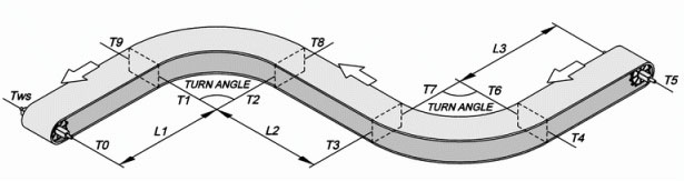
The serial turning conveyor system is constructed of two 90 degree conveyors with opposite direction. The wearstrips in return way and carry way are both made of HDPE material. The width of conveyor belt is 300mm; it adopts HS-300B belt and sprockets with12 teeth. The length of the straight running section is 2M at the idler end, 600mm in jointing area, and 2M at the drive end. Its inside radius is 750mm. The friction factor of wearstrips and the belt is 0.15. The transporting objects are plastic boxes at 40Kg/M2. The conveyor operation speed is 5M/min, and it operates in the dry environment. The related calculations are as follows.
-
Calculation of unit total tension - TWS
|
FORMULA : |
TWS = ( TN ) |
|
|
T0 = 0 |
| Total tension of the drive section in the carrying way. | |
|
|
T1 = WB + FBW × LR × WB |
|
|
T1 = 5.9 + 0.35 × 2 × 5.9 = 10.1 |
|
FORMULA : |
TN = ( Ca × TN-1 ) + ( Cb × FBW × RO ) × WB |
| Tension of the turning section in the return way. For the value Ca and Cb, please refer to Table Fc. | |
| T2 = ( Ca × T2-1 ) + ( Cb × FBW × RO ) × WB | |
| T2 = ( Ca × T1 ) + ( Cb × FBW × RO ) × WB | |
| T2 = ( 1.27 × 10.1 ) + ( 0.15 × 0.35 × 1.05 ) × 5.9 = 13.15 | |
|
FORMULA : |
TN = TN-1 + FBW × LR × WB |
| Tension of the straight section in the return way. | |
|
T3 = T3-1 + FBW × LR × WB |
|
|
T3 = T2 + FBW × LR × WB |
|
|
T3 = 13.15 + ( 0.35 × 0.6 × 5.9 ) = 14.3 |
|
|
FORMULA : |
TN = ( Ca × TN-1 ) + ( Cb × FBW × RO ) × WB |
| Tension of the turning section in the return way. For the value Ca and Cb, please refer to Table Fc. | |
|
T4 = ( Ca × T4-1 ) + ( Cb × FBW × RO ) × WB |
|
|
TN = ( Ca × T3 ) + ( Cb × FBW × RO ) × WB |
|
| T4 = ( 1.27 × 14.3 ) + ( 0.15 × 0.35 × 1.05 ) × 5.9 = 18.49 | |
|
FORMULA : |
TN = TN-1 + FBW × LR × WB |
| Tension of the straight section in the return way. | |
|
T5 = T5-1 + FBW × LR × WB |
|
|
T5 = T4 + FBW × LR × WB |
|
| T5 = 18.49 + ( 0.35 × 2 × 5.9 ) = 22.6 | |
|
FORMULA : |
TN = TN-1 + FBW × LP × ( WB + WP ) |
| Tension of the straight section in the carrying way. | |
| T6 = T6-1 + FBW × LP × ( WB + WP ) | |
| T6 = T5 + FBW × LP × ( WB + WP ) | |
| T6 = 22.6 + [ ( 0.35 × 2 × ( 5.9 + 40 ) ] = 54.7 | |
|
FORMULA : |
TN = ( Ca × TN-1 ) + ( Cb × FBW × RO ) × ( WB + WP ) |
| Tension of the turning section in the carrying way. For the value Ca and Cb, please refer to Table Fc | |
|
T7 = ( Ca × T7-1 ) + ( Cb × FBW × RO ) × ( WB + WP ) |
|
|
T7 = ( Ca × T6 ) + ( Cb × FBW × RO ) × ( WB + WP ) |
|
| T7 = ( 1.27 × 54.7 ) + ( 0.15 × 0.35 × 1.05 ) × ( 40 + 5.9 ) = 72 | |
|
FORMULA : |
TN = TN-1 + FBW × LP × ( WB + WP ) |
| Tension of the straight section in the carrying way. | |
|
T8 = T8-1 + FBW × LP × ( WB + WP ) |
|
|
TN = T7 + FBW × LP × ( WB + WP ) |
|
| T8 = 72 + [ ( 0.35 × 0.5 × ( 40 + 5.9 ) ] = 80 | |
|
FORMULA : |
TN = ( Ca × TN-1 ) + ( Cb × FBW × RO ) × ( WB + WP ) |
| Tension of the turning section in the carrying way. For the value Ca and Cb, please refer to Table Fc | |
|
T9 = ( Ca × T9-1 ) + ( Cb × FBW × RO ) × ( WB + WP ) |
|
|
T9 = ( Ca × T8 ) + ( Cb × FBW × RO ) × ( WB + WP ) |
|
| T9 = ( 1.27 × 80 ) + ( 0.15 × 0.35 × 1.05 ) × ( 40 + 5.9 ) =104 |
- Total belt tension TWS (T6)
|
FORMULA : |
TWS = T10 |
| Total tension of the straight section in the carrying way. | |
|
TN = TN-1 + FBW × LP × ( WB + WP ) |
|
|
T10 = T10-1 + FBW × LP × ( WB + WP ) |
|
|
T10 = 104 + 0.35 × 2 × ( 5.9 + 40 ) = 136.13 ( Kg / M ) |
-
Calculation of unit allowable tension - TA
|
FORMULA : |
TA = BS × FS × FT |
| TA = 2118 × 1.0 × 0.95 = 2012 ( Kg / M ) | |
| Due to value TA is larger than TW; therefore, adopting Series 300B conveyor belt is a safe and proper selection. |
-
Please refer to Sprocket spacing in Drive Sprockets Chapter; the maximum sprocket spacing is approximately 145mm.
-
Deflection ratio of drive shaft - DS
|
FORMULA : |
SL = ( TWS + SW ) × BW |
| SL = ( 136.13 + 11.48 ) × 0.3 = 44.28 ( Kg ) | |
|
FORMULA : |
DS = 5 × 10⁻⁴ × [ ( SL × SB3 ) / ( E x I ) ] |
| DS = 5 × 10⁻⁴ ×[ ( 44.28 × 4003 ) / ( 19700 × 174817 ) = 0.000001 ( mm ) | |
| If the calculation result is smaller than the standard value that listed in the Deflection Table; adopting two ball bearings is enough for the system. |
-
Calculation of shaft torque - Ts
|
FORMULA : |
TS = TWS × BW × R |
| TS = 136.3 × 0.3 × 92.5 = 3782.3 ( kg - mm ) | |
| In comparison with the Maximum Torque Factor in Shaft Selection unit, we know that the use of 38mm × 38mm square shaft is safe and proper selection. |
-
Calc, ulat, io, n of horsepower - HP
|
FORMULA : |
HP = 2.2 × 10⁻⁴ × [ ( TS × V ) / R ] |
| HP = 2.2 × 10⁻⁴ × [ ( 3782.3 × 5 ) / 92.5 ] = 0.045 ( HP ) | |
| In general, the mechanical energy of center drive conveyor may lost about 30% during the operation. | |
| MHP = [ 0.045 / ( 100 - 30 ) ] × 100 = 0.06 ( HP ) | |
| Adopting the 1/4HP drive motor is the right selection. |
Spiral Conveyor
The pictures shows above is an example of the spiral conveyor system with three layers. The wearstrips of the carrying way and return way are made of HDPE material. The total belt width is 500mm and adopt HS-300B-HD and the sprockets with 8 teeth. The length of the straight carrying section in the drive and idler end is 1 meter respectively. Its inside turning radius is 1.5M, and transporting objects are the mail boxes at 50Kg/M2. The operating speed of the conveyor is 25M/min, incline to the height of 4M and operate in the dry environment. The related calculations are as follows.
-
Calculation of unit total tension - TWS
|
FORMULA : |
TW = TB × FA |
|
|
TWS = 958.7 × 1.6 = 1533.9 ( Kg / M ) |
|
|
|
|
FORMULA : |
TB = [ 2 × R0 × M + ( L1 + L2 ) ] ( WP + 2 WB ) × FBW + ( WP × H ) |
|
|
TB = [ 2 × 3.1416 × 2 × 3 + ( 1 + 1 ) ] ( 50 + 2 × 5.9 ) × 0.35 + ( 50 × 2 ) |
| TB = 958.7 ( Kg / M ) |
- Calculation of unit allowable tension - TA
|
FORMULA : |
TA = BS × FS × FT |
| TA = 2118 × 1.0 × 0.95 = 2012 ( Kg / M ) | |
| Because of value TA is larger than TW; therefore, adopt Series 300B-HD belt is a safe and proper selection. |
- Please refer to Sprocket spacing of HS-300 in Drive Sprockets Chapter; the maximum sprocket spacing is approximately 145mm.
- Deflection ratio of drive shaft - DS
|
FORMULA : |
SL = ( TWS + SW ) × BW |
| SL = ( 1533.9 + 11.48 ) × 0.5 = 772.7 ( Kg ) | |
|
FORMULA : |
DS = 5 × 10⁻⁴ ×[ ( SL × SB3 ) / ( E × I ) ] |
| DS = 5 × 10⁻⁴ ×[ ( 772.7 × 6003 ) / ( 19700 ×174817 ) ] = 0.024 ( mm ) |
- If the calculation result is smaller than the standard value that listed in the Deflection Table; adopting two ball bearings is enough for the system.
- Calculation of shaft torque - TS
|
FORMULA : |
TS = TWS × BW × R |
| TS = 1533.9 × 0.5 × 92.5 = 70942.8 ( kg - mm ) | |
| In comparison with the Maximum Torque Factor in Shaft Selection unit, we know that the use of 38mm × 38mm square shaft is safe and proper selection. |
- Calculation of horsepower - HP
|
FORMULA : |
HP = 2.2 × 10⁻⁴ × [ ( TS × V ) / R ] |
| HP = 2.2 × 10⁻⁴ × [ ( 70942.8 × 4 ) / 60 = 1.04 ( HP ) | |
| In general, the mechanical energy of center drive conveyor may lost about 40% during the operation. | |
| MHP = [ 1.04 / ( 100 - 40 ) ] × 100 = 1.73 ( HP ) | |
| Adopting the 2HP drive motor is the right selection. |