Units Conversion
|
English (USA) Unit X |
Multiply by |
= Metric Unit |
X Multiply by |
= English (USA) Unit |
||
|
Linear Measure |
in |
25.40 |
mm |
0.0394 |
in |
Linear Measure |
|
in |
0.0254 |
m |
39.37 |
in |
||
|
ft |
304.8 |
mm |
0.0033 |
ft |
||
|
ft |
0.3048 |
m |
3.281 |
ft |
||
|
Square Measure |
in2 |
645.2 |
mm2 |
0.00155 |
in2 |
Square Measure |
|
in2 |
0.000645 |
m2 |
1550.0 |
in2 | ||
|
ft2 |
92.903 |
mm2 |
0.00001 |
ft2 |
||
|
ft2 |
0.0929 |
m2 |
10.764 |
ft2 |
||
|
Cubic Measure |
ft3 |
0.0283 |
m3 |
35.31 |
ft3 |
Cubic Measure |
|
ft3 |
28.32 |
L |
0.0353 |
ft3 |
||
| Speed Rate |
ft / s |
18.29 |
m / min |
0.0547 |
ft / s |
Speed Rate |
|
ft / min |
0.3048 |
m / min |
3.281 |
ft / min |
||
|
Avoirdupois Weight |
lb |
0.4536 |
kg |
2.205 |
lb |
Avoirdupois Weight |
|
lb / ft3 |
16.02 |
kg / m3 |
0.0624 |
lb / ft3 |
||
|
Bearing Capacity |
lb |
0.4536 |
kg | 2.205 |
lb |
Bearing Capacity |
|
lb |
4.448 |
Newton (N) |
0.225 |
lb |
||
|
kg |
9.807 |
Newton (N) |
0.102 |
kg |
||
|
lb / ft |
1.488 |
kg / m |
0.672 |
lb / ft |
||
|
lb / ft |
14.59 |
N / m |
0.0685 |
lb / ft | ||
|
kg - m |
9.807 |
N / m |
0.102 |
kg - m |
||
|
Torque |
in - lb |
11.52 |
kg - mm |
0.0868 |
in - lb |
Torque |
|
in - lb |
0.113 |
N - m |
8.85 |
in - lb |
||
|
kg - mm |
9.81 |
N - mm |
0.102 |
kg - mm |
||
|
Rotate Inertia |
in4 |
416.231 |
mm4 |
0.0000024 |
in4 |
Rotate Inertia |
|
in4 |
41.62 |
cm4 |
0.024 |
in4 |
||
|
Pressure /Stress |
lb / in2 |
0.0007 |
kg / mm2 |
1422 |
lb / in2 |
Pressure / Stress |
|
lb / in2 |
0.0703 |
kg / cm2 |
14.22 |
lb / in2 |
||
|
lb / in2 |
0.00689 |
N / mm2 |
145.0 |
lb / in2 |
||
|
lb / in2 |
0.689 |
N / cm2 |
1.450 |
lb / in2 |
||
|
lb / ft2 |
4.882 |
kg / m2 |
0.205 |
lb / ft2 |
||
|
lb / ft2 |
47.88 |
N / m2 |
0.0209 |
lb / ft2 |
||
|
Power |
HP |
745.7 |
watt |
0.00134 |
HP |
Power |
|
ft - lb / min |
0.0226 |
watt |
44.25 |
ft - lb / min |
||
|
Temperature |
°F |
T C = ( °F - 32 ) / 1.8 |
Temperature |
|||
Symbol of B D E F
|
Symbol |
Unit |
|
|
BS |
Conveyor Belt Tensile Strength |
Kg/M |
|
BW |
Belt Width |
M |
C Symbol Definition
|
Symbol |
Unit |
|
|
Ca |
See the Table FC |
---- |
|
Cb |
See the Table FC |
---- |
D Symbol Definition
|
Symbol |
Unit |
|
| DS |
Shaft Deflection Ratio |
mm |
E Symbol Definition
|
Symbol |
Unit |
|
| E |
Shaft Elongation Rate |
Gpa |
F Symbol Definition
|
Symbol |
Unit |
|
| FC |
Friction Coefficient Between Belt Edge and Hold Down Strip |
---- |
| FBP |
Friction Coefficient Between Carry Product and Belt Surface |
---- |
| FBW |
Friction Coefficient of Belt Support Material |
---- |
| FA |
Coefficient Amended |
---- |
| FS |
Tensile Strength Coefficient Amended |
---- |
| FT |
Conveyor Belt Temperature Coefficient Amended |
--- |
Symbol of H I L M
|
Symbol |
Unit |
|
| H |
Elevation Conveyor incline altitude. |
m |
| HP |
Horsepower |
HP |
I Symbol Definition
|
Symbol |
Unit |
|
| I |
Moment Of Inertia |
mm4 |
L Symbol Definition
|
Symbol |
Unit |
|
| L |
Conveyance Distance (Center Point From Drive Shaft To Idler Shaft) |
M |
| LR |
Return Way Straight Run Section Length |
M |
| LP |
Carry Way Straight Run Section Length |
M |
M Symbol Definition
|
Symbol |
Unit |
|
| M |
Spiral Conveyor Layer Level |
---- |
| MHP |
Motor Horsepower |
HP |
Symbol of P R S
|
Symbol |
Unit |
|
| PP |
Product Accumulated Measure Area Percentage of Carry Way |
---- |
R Symbol Definition
|
Symbol |
Unit |
|
| R |
Sprocket Radius |
mm |
| RO |
Outside Radius |
mm |
| rpm |
Revolutions Per Minute |
rpm |
S Symbol Definition
|
Symbol |
Unit |
|
| SB |
Interval Between Bearing |
mm |
| SL |
Shaft Total Loading |
Kg |
| SW |
Shaft Weight |
Kg/M |
Symbol of T V W
|
Symbol |
Unit |
|
| TA |
Conveyor Belt Unit Allowable Tension |
Kg/M |
| TB |
Conveyor Belt Unit Theory Tension |
Kg/M |
| TL |
Conveyor Belt Unit Catenary's Sag tension. |
Kg/M |
| TN |
Tension Of Section |
kg/M |
| TS |
Torque |
Kg.mm |
| TW |
Conveyor Belt Unit Total Tension |
Kg/M |
| TWS |
Particular Type Conveyor Belt Unit Total Tension |
Kg/M |
V Symbol Definition
|
Symbol |
Unit |
|
| V |
Conveyance Speed |
M/min |
| VS |
Theory Speed |
M/min |
W Symbol Definition
|
Symbol |
Unit |
|
| WB |
Conveyor Belt Unit Weight |
Kg/M2 |
| Wf |
Accumulated Conveyance Friction Stress |
Kg/M2 |
| WP |
Conveyor Belt Carry Product Unit Weight |
|
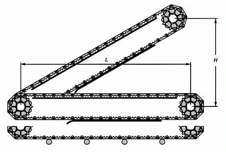
Pusher And Bidirectional
For the pusher or bidirectional conveyor, the belt tension will be higher than the ordinary horizontal conveyor; therefore, the shafts at two ends are necessary to be considered as drive shafts and subsumed in the calculation. In general, it is approximate 2.2 times the experience factor to get the total belt tension.
FORMULA: TWS = 2.2 TW = 2.2 TB X FA
TWS in this unit means the tension calculation of the bidirectional or pusher conveyor.
Turning Calculation
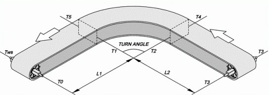
The tension calculation TWS of the turning conveyor is to calculate the accumulated tension. Therefore, the tension in every carrying section will affect the value of total tension. That means, the total tension is accumulated from the the beginning of the drive section in return way, along the return way to the idler section, and then pass through the carrying section to the drive section.
The design point in this unit is T0 that under the drive shaft. The value of T0 is equal to zero; we calculate every section from T0. For example, the first straight section in return way is from T0 to T1, and that means the accumulated tension of T1.
T2 is the accumulated tension of the turning position in the return way; in another word, it is the accumulated tension of T0, T1 and T2. Please according to the illustration above and figure out the accumulated tension of the latter sections.
FORMULA: TWS = ( T6 )
Total tension of the drive section in the carrying way.
TWS in this unit means the tension calculation of the turning conveyor.
FORMULA: T0 = 0
T1 = WB + FBW X LR X WB
Tension of catenary sag at the drive position.
FORMULA: TN = ( Ca X TN-1 ) + ( Cb X FBW X RO ) X WB
Tension of the turning section in the return way.
For the value Ca and Cb, please refer to Table Fc.
T2 = ( Ca X T2-1 ) + ( Cb X FBW X RO ) X WB
TN = ( Ca X T1 ) + ( Cb X FBW X RO ) X WB
FORMULA: TN = TN-1 + FBW X LR X WB
Tension of the straight section in the return way.
T3 = T3-1 + FBW X LR X WB
T3 = T2 + FBW X LR X WB
FORMULA: TN = TN-1 + FBW X LP X ( WB + WP )
Tension of the straight section in the carrying way.
T4 = T4-1 + FBW X LP X ( WB + WP )
T4 = T3 + FBW X LP X ( WB + WP )
FORMULA: TN = ( Ca X TN-1 ) + ( Cb X FBW X RO ) X ( WB + WP )
Tension of the turning section in the carrying way.
For the value Ca and Cb, please refer to Table Fc.
T5 = ( Ca X T5-1 ) + ( Cb X FBW X RO ) X ( WB + WP )
T5 = ( Ca X T4 ) + ( Cb X FBW X RO ) X ( WB + WP )
Spiral Conveyor
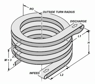
FORMULA: TWS = TB × FA
TWS in this unit means the tension calculation of spiral conveyor.
FORMULA: TB = [ 2 × RO × M + ( L1 + L2 ) ] ( WP + 2WB ) × FBW + ( WP × H )
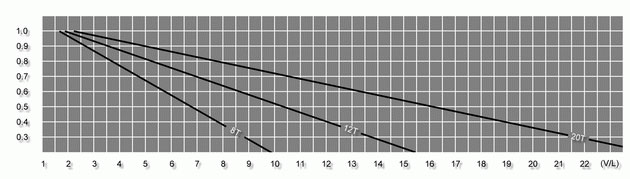
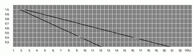
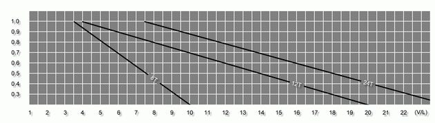
FORMULA: TA = BS × FS × FT
Please refer to Table FT and Table FS.
Practical Example
The comparison of TA and TB, and other related calculations are the same as other types of conveyors. There are certain restrictions and regulations on the design and construction of the spiral conveyor. Therefore, while applying HONGSBELT spiral or turning belts to spiral conveyor system, we recommend you to refer to HONGSBELT Engineering manual and contact with our technical service department for further information and details.
Unit Tension
FORMULA: TB = [ ( WP + 2WB ) X FBW ] X L + ( WP X H )
If carrying products are with the characteristic of piling up, the friction force Wf that increases during the piling up conveyance should be subsume to the calculation.
FORMULA: TB = [ ( WP + 2WB ) X FBW + Wf ] X L + ( WP X H )
FORMULA: Wf = WP X FBP X PP
Allowable Tension
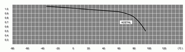
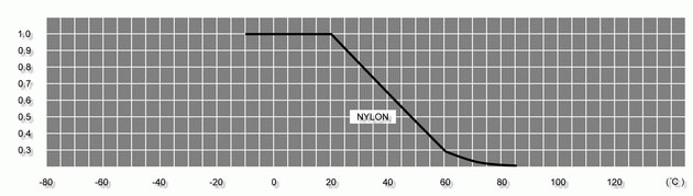
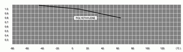
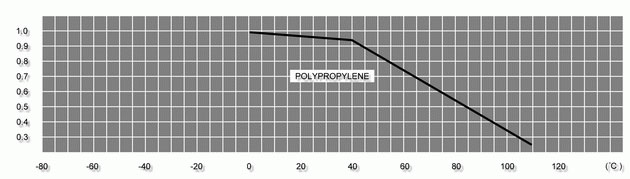
Due to the different material of belt has different tensile strength that will be affected by temperature variation. Therefore, the calculation of unit allowable tension TA can be used to contrast with the belt total tension TW. This calculation result will help you to make the right choice of belt selection and match the demands of the conveyor. Please refer to Table FS and Table Ts in left menu.
FORMULA: TA = BS X FS X FT
BS = Conveyor Belt Tensile Strength ( Kg / M )
FS and FT Refer to Table FS and Table FT
Table Fs
Series HS-100
Series HS-200
Series HS-300
Series HS-400
Series HS-500
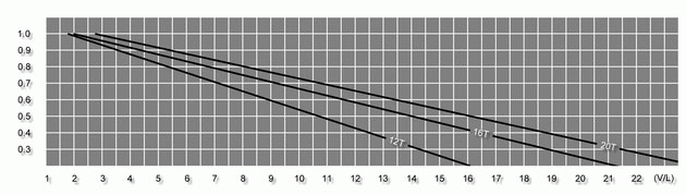
Table Ts
Acetal
Nylon
Polyethylene
Polypropylene
Shaft Selection
FORMULA: SL = ( TW + SW ) ?BW
Driven / Idler Shaft Weight Table - SW
| Shaft Dimensions | Shaft Weight ( Kg/M ) | |||
| Carbon Steel | Stainless Steel | Aluminum Alloy | ||
| Square shaft | 38mm | 11.33 | 11.48 | 3.94 |
| 50mm | 19.62 | 19.87 | 6.82 | |
| Round Shaft | 30mm?/FONT> | 5.54 | 5.62 | 1.93 |
| 45mm?/FONT> | 12.48 | 12.64 | 4.34 | |
Deflection of Drive / Idler Shaft - DS
Without Intermediate Bearing
FORMULA :
DS = 5 ?10-4 ( SL ?SB3 / E ?/FONT> I )
With Intermediate Bearing
FORMULA :
DS = 1 ?10-4 ( SL ?SB3 / E ?I )
Elasticity of Drive Shaft - E
|
Unit : Kg/mm2 |
|||
| Material | Stainless Steel | Carbon Steel | Aluminum Alloy |
| Drive Shaft Elastic Rate | 19700 | 21100 | 7000 |
Inertia Moment - I
| Bore diameter of drive sprocket | Inertia moment of shaft ( mm4 ) | |
| Square Shaft | 38mm | 174817 |
| 50mm | 1352750 | |
| Round Shaft | 30mm?/FONT> | 40791 |
| 45mm?/FONT> | 326741 | |
Drive Shaft Torque Calculation - TS
|
FORMULA : |
TS = TW ?BW ?R |
For the calculation value above, please compare with the table below for selecting the best drive shaft. If the torque of the drive shaft is still too strong, the smaller sprocket can be used to reduce the torque, and also economize the prime cost of shaft and bearing.
Using the smaller sprocket to fit the drive shaft that with the bigger diameter to reduce the torque, or using the bigger sprocket to fit the drive shaft that with the smaller diameter to increase torque.
Maximum Torque Factor for Drive Shaft
| Torque | Material | Journal Diameter (mm) | ||||||
| 50 | 45 | 40 | 35 | 30 | 25 | 20 | ||
|
Kg-mm x 1000 |
Stainless Steel | 180 | 135 | 90 | 68 | 45 | 28 | 12 |
| Carbon Steel | 127 | 85 | 58 | 45 | 28 | 17 | 10 | |
| Aluminum Alloy | -- | -- | -- | 28 | 17 | 12 | 5 | |
Horsepower
If the drive motor is selected for a gear reducer motor, the horsepower ratio should be greater than the carrying products and the total tensile force that generates during the belt running.
Horse Power (HP)
|
FORMULA : |
= 2.2 × 10⁻⁴ × TW × BW × V |
| = 2.2 × 10⁻⁴ ( TS × V / R ) | |
| = Watts × 0.00134 |
Watts
| FORMULA : | = ( TW × BW × V ) / ( 6.12 × R ) |
| = ( TS × V ) / ( 6.12 × R ) | |
| = HP × 745.7 |
Table FC
| Rail Material | Temperature | FC | ||
| Belt Material | Dry | Wet | ||
| HDPE / UHMW | -10°C ~ 80°C | P.P. | 0.10 | 0.10 |
| P.E. | 0.30 | 0.20 | ||
| Actel | 0.10 | 0.10 | ||
| Nylon | 0.35 | 0.25 | ||
| Acetal | -10°C ~ 100°C | P.P. | 0.10 | 0.10 |
| P.E. | 0.10 | 0.10 | ||
| Actel | 0.10 | 0.10 | ||
| Nylon | 0.20 | 0.20 | ||
Please contrast the rails material and belt material of the conveyor with the transporting procedure in dry or wet environment to get value FC.
Ca, Cb Value
| Conveyor Belt Turning Angle | Friction Coefficient Between Conveyor Belt Edge & Rail Strip | |||||
| FC ≤ 0.15 | FC ≤ 0.2 | FC ≤ 0.3 | ||||
| Ca | Cb | Ca | Cb | Ca | Cb | |
| ≥ 15 ° | 1.04 | 0.023 | 1.05 | 0.021 | 1.00 | 0.023 |
| ≥ 30 ° | 1.08 | 0.044 | 1.11 | 0.046 | 1.17 | 0.048 |
| ≥ 45 ° | 1.13 | 0.073 | 1.17 | 0.071 | 1.27 | 0.075 |
| ≥ 60 ° | 1.17 | 0.094 | 1.23 | 0.096 | 1.37 | 0.10 |
| ≥ 90 ° | 1.27 | 0.15 | 1.37 | 0.15 | 1.6 | 0.17 |
| ≥ 180 ° | 1.6 | 0.33 | 1.88 | 0.37 | 2.57 | 0.44 |
After getting value FC from Table FC, please contrast it with the curved angle of the conveyor, and you can get value Ca and value Cb.