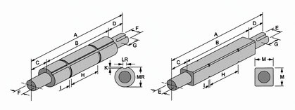
Drive / Idler Shaft
HONGSBELT drive/idler shaft can be constructed by stainless steel, carbon steel and aluminum alloy materials; these three materials are recommended to use mostly.The appearance of shaft is designed in two types which are the square shaft and the round shaft respectively. The shaft length must be manufactured according to the effective width of belt and all related dimension of conveyor structure required.
unit : mm
|
Frame |
A | B | C | D | E(max.) | F(max.) | G | H | I | K | LR | M | MR |
| 25.4 | B+130 | 50 | 80 | 25 | 25 | 45 | 2 | 4.5 | 7.2 | 38 | 29 | ||
| 31.8 | B+140 | 60 | 80 | 25 | 25 | 45 | 4.5 | 7.2 | 38 | 29 | |||
| 38.1 | B+200 | 75 | 125 | 25 | 25 | 65 | 4.5 | 8.2 | 38 | 45 | |||
| 50.4 | B+255 | 85 | 170 | 35 | 35 | 106 | 4.5 | 8.2 | 38 | 45 | |||
| 63.5 | B+285 | 100 | 185 | 35 | 35 | 125 | 4.5 | 8.2 | 38 | 45 | |||
| 70.0 | B+310 | 110 | 200 | 45 | 40 | 136 | 5.5 | 10.2 | 50.8 | 45 | |||
| 80.0 | B+355 | 125 | 230 | 45 | 40 | 146 | 5.5 | 10.2 | 50.8 | -- | |||
| 90.0 | B+400 | 140 | 260 | 45 | 40 | 165 | 5.5 | 10.2 | 50.8 | -- |
The design specification above is for reference only.
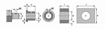
Water Proof Bearing
unit :mm
|
EASE Model |
Bearing Model |
Journal |
Journal Sleeve of TEFLON |
TEFLON Bearing |
|||||||||
| UCF | UXF | A | B | C | D | E | F | G | H | I | J | K | |
| TEF-1 | 201 | - - |
11.97(12) |
12 | 2.8 | 5 | 25 | 3 | 18 | 3 | 16 | 25 | 60 |
| TEF-2 | 202 | - - |
14.97(15) |
15 | 2.8 | 5 | 25 | 3 | 21 | 3 | 16 | 25 | 60 |
| TEF-3 | 203 | - - | 16.97(17) | 17 | 2.8 | 5 | 25 | 3 | 23 | 3 | 16 | 25 | 60 |
| TEF-4 | 204 | - - | 19.95(20) | 20 | 2.8 | 5 | 35 | 3 | 26 | 14.5 | 35 | 65 | 55 |
| TEF-5 | 205 | 05 | 24.95(25) | 25 | 3.8 | 5 | 35 | 3 | 33 | 18.5 | 35 | 80 | 70 |
| TEF-6 | 206 | 06 | 29.95(30) | 30 | 3.8 | 5 | 35 | 3 | 38 | 16 | 34 | 80 | 70 |
| TEF-7 | 207 | 07 | 34.95(35) | 35 | 3.8 | 8 | 35 | 3 | 43 | 18.5 | 35 | 90 | 80 |
| TEF-8 | 208 | 08 | 39.95(40) | 40 | 3.8 | 8 | 45 | 3 | 48 | 16 | 45 | 90 | 80 |
| TEF-9 | 209 | 09 | 44.95(45) | 45 | 4.8 | 8 | 45 | 3 | 55 | 22.5 | 45 | 120 | 100 |
The processing tolerance of stainless steel journal and TEFLON journal is ± 0.05 mm.
The processing tolerance of TEFLON bearing is ± 0.1 mm.
The water proof bearing should be applied within the average loading of 45 Kg / m2 and the speed of conveyor belt has to lower than18M per/minute in the safety range.
For the examples of real application, please refer to Examples in top menu.
Auxiliary Bearing
When the length of drive/idler shaft journal is over 950mm or in heavy loading operation , the drive/idler shaft will be deformed by the huge tension. The allowable maximum deformation ratio is 2.5mm for drive shaft, and 5.5mm for idler shaft. For increasing the shaft length and decreasing the torque waste, it is necessary to install auxiliary bearings between the shafts on both sides to support the center position of drive/idler shaft. It will avoid the deformation and deflection of drive/idler shaft.
If it is necessary to adopt the intermediate auxiliary bearing or not, please refer to Deflection Table in left menu.
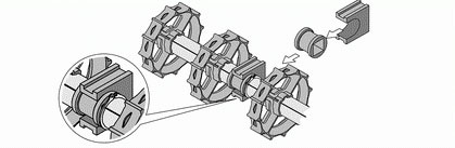
Notes for Intermediate Auxiliary Bearing Installation
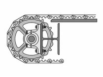
For intermediate auxiliary bearings installation, the auxiliary bearing must be joined on the frame of conveyor side by welding, or fixed by built-in screws. The integral conveyor structure should be manufactured with the precise plan and sophisticated construction. Please pay attention to the diameter of drive sprocket and make sure if it is able to contain the installation of intermediate auxiliary bearing. Please refer to Split Bearing Dimension Comparison Table below.
The intermediate auxiliary bearings always adopt the split bearings. It is easy to install, maintain, and endure heavy loading. The joint of split bearing should be perpendicular to the transporting direction of belt, in order to increase the tensile strength of the drive or idler shaft. While adopting the intermediate auxiliary bearing, please choose the products which are able to endure the bidirectional loading for radial and axial.
The conventional ball bearing is also available to use the round bore adapter as a supporting device to instead of the intermediate auxiliary bearing. For the processing dimension of round bore adapter, please refer to Split Bearing Dimension Table below.
Split Bearing Dimension Table
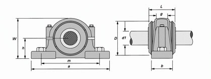
Unit : mm
| d1 | d | a | b | c | g | h | l | w | M | S |
| 35 | 80 | 205 | 60 | 25 | 33 | 60 | 85 | 110 | 170 | M 12 |
| 40 | 85 | 205 | 60 | 25 | 31 | 60 | 85 | 112 | 170 | M 12 |
| 45 | 90 | 205 | 60 | 25 | 33 | 60 | 90 | 115 | 170 | M 12 |
| 50 | 100 | 205 | 70 | 28 | 33 | 70 | 95 | 130 | 210 | M 16 |
Simple Auxiliary Bearing
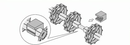
When conveyor belt is driven by the sprocket with smaller diameter or operated in humid and low temperature environment, we recommend you to adopt another type of the simple auxiliary bearing to substitute for the split bearing.
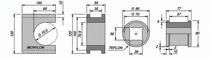
Examples
unit : mm
| A | B | C | D1 |
| 55 | 70 | 100 | 35 |
| 60 | 85 | 110 | 40 |
| 75 | 100 | 120 | 45 |
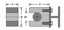
Bracket Auxiliary
The bracket auxiliary bearing is designed for heavy loading, intermittent operation, the environment with temperature difference more than 40°C, and the drive/idler shaft that must install the auxiliary bearing.
Example of Bracket Auxiliary Bearing Construction
The illustration is shown above provides the example of 38mm only. You can refer to the dimensions above to fabricate these accessories yourself. For other dimensions, please contact with HONGSBELT technical department and the local agencies for further information. We are willing to give service to you.
Shaft Deflection Table
| Material |
Shaft |
Aided Bearing |
The Length of The Shaft ( mm ) |
|||||||||||||||||
|
500 |
750 |
1000 |
1250 |
1500 |
1750 |
2000 |
2250 |
2500 |
2750 |
3000 |
3250 |
3500 |
3750 |
4000 |
||||||
|
D |
N |
2800 |
900 |
650 |
375 |
300 |
150 |
95 |
65 |
45 |
35 |
-- |
-- |
-- |
-- |
-- |
||||
|
Y |
-- |
-- |
3750 |
1750 |
1000 |
750 |
400 |
275 |
200 |
150 |
100 |
75 |
65 |
60 |
50 |
|||||
|
I |
N |
-- |
2800 |
1500 |
750 |
475 |
300 |
180 |
120 |
80 |
60 |
45 |
40 |
-- |
-- |
-- |
||||
|
Y |
-- |
-- |
-- |
4000 |
2250 |
1750 |
1000 |
750 |
450 |
350 |
250 |
175 |
150 |
130 |
110 |
|||||
|
D |
N |
-- |
-- |
1750 |
1000 |
750 |
450 |
300 |
200 |
140 |
90 |
60 |
50 |
45 |
40 |
30 |
||||
|
Y |
-- |
-- |
-- |
4500 |
3500 |
2250 |
1750 |
750 |
500 |
350 |
250 |
180 |
150 |
100 |
90 |
|||||
|
I |
N |
-- |
-- |
4500 |
2500 |
1500 |
820 |
500 |
350 |
225 |
165 |
135 |
100 |
75 |
-- |
-- |
||||
|
Y |
-- |
-- |
-- |
-- |
-- |
4500 |
3000 |
1900 |
1200 |
750 |
450 |
400 |
300 |
265 |
250 |
|||||
|
D |
N |
1750 |
750 |
350 |
150 |
80 |
45 |
35 |
25 |
15 |
10 |
-- |
-- |
-- |
-- |
-- |
||||
|
Y |
-- |
3000 |
1750 |
750 |
450 |
250 |
160 |
110 |
70 |
50 |
-- |
-- |
-- |
-- |
-- |
|||||
|
I |
N |
-- |
2500 |
1000 |
500 |
250 |
100 |
50 |
30 |
25 |
20 |
-- |
-- |
-- |
-- |
-- |
||||
|
Y |
-- |
-- |
4000 |
2000 |
900 |
750 |
450 |
300 |
190 |
100 |
80 |
60 |
-- |
-- |
-- |
|||||
|
D |
N |
-- |
-- |
-- |
4500 |
1750 |
125 |
750 |
450 |
350 |
225 |
200 |
150 |
100 |
75 |
-- |
||||
|
Y |
-- |
-- |
-- |
-- |
-- |
5000 |
3500 |
2250 |
1850 |
1000 |
750 |
500 |
450 |
400 |
350 |
|||||
|
I |
N |
-- |
-- |
3500 |
2500 |
1500 |
850 |
500 |
350 |
225 |
200 |
100 |
90 |
75 |
-- |
-- |
||||
|
Y |
-- |
-- |
-- |
-- |
-- |
4500 |
3000 |
2000 |
1000 |
750 |
500 |
400 |
350 |
300 |
250 |
|||||
|
D |
N |
2940 |
950 |
690 |
395 |
315 |
160 |
100 |
70 |
50 |
40 |
30 |
-- |
-- |
-- |
-- |
||||
|
Y |
-- |
-- |
4000 |
1840 |
1150 |
790 |
420 |
290 |
50 |
160 |
105 |
80 |
70 |
65 |
55 |
|||||
|
I |
N |
-- |
2940 |
1575 |
790 |
500 |
315 |
190 |
130 |
210 |
65 |
50 |
45 |
-- |
-- |
-- |
||||
|
Y |
-- |
-- |
-- |
4200 |
2370 |
1840 |
1050 |
790 |
85 |
365 |
255 |
190 |
160 |
140 |
120 |
|||||
|
D |
N |
-- |
-- |
1850 |
1150 |
790 |
475 |
315 |
210 |
475 |
95 |
65 |
55 |
50 |
45 |
35 |
||||
|
Y |
-- |
-- |
-- |
4750 |
3675 |
2365 |
1840 |
790 |
150 |
370 |
260 |
185 |
160 |
120 |
100 |
|||||
|
I |
N |
-- |
-- |
4750 |
2650 |
1580 |
865 |
525 |
370 |
530 |
175 |
140 |
110 |
80 |
-- |
-- |
||||
|
Y |
-- |
-- |
-- |
-- |
-- |
4730 |
3150 |
1995 |
240 |
790 |
470 |
420 |
350 |
300 |
270 |
|||||
|
D |
N |
1850 |
790 |
370 |
160 |
84 |
50 |
40 |
50 |
15 |
10 |
-- |
-- |
-- |
-- |
-- |
||||
|
Y |
-- |
3150 |
185 |
790 |
475 |
260 |
170 |
120 |
75 |
50 |
-- |
-- |
-- |
-- |
-- |
|||||
|
I |
N |
-- |
2625 |
1050 |
120 |
260 |
105 |
55 |
30 |
25 |
20 |
-- |
-- |
-- |
-- |
-- |
||||
|
Y |
-- |
-- |
4200 |
2100 |
950 |
790 |
480 |
320 |
200 |
105 |
85 |
65 |
-- |
-- |
-- |
|||||
|
D |
N |
-- |
-- |
-- |
4725 |
1850 |
1300 |
790 |
480 |
370 |
250 |
210 |
175 |
105 |
90 |
--- |
||||
|
Y |
-- |
-- |
-- |
-- |
-- |
5250 |
3700 |
2400 |
2000 |
1050 |
790 |
525 |
475 |
425 |
375 |
|||||
|
I |
N |
-- |
-- |
3675 |
2650 |
1580 |
900 |
550 |
370 |
250 |
210 |
105 |
105 |
90 |
-- |
-- |
||||
|
Y |
-- |
-- |
-- |
-- |
-- |
4800 |
3150 |
2100 |
1050 |
790 |
525 |
420 |
375 |
315 |
265 |
|||||
D = Drive, I = Idle, N = Not, Y = Yes