Notes for Catenary Sag
When the belt is running, it is quite important to keep a proper tension, the appropriate length of the belt, and none of any missing engagement between belt and sprockets. When the conveyor is operating, the extra length will be absorbed by the catenary sag in the return way in order to maintain suitable tension for belt pull.
If the conveyor belt has the excessive length on the return way, the drive/Idler sprocket will have the missing engagement with the belt, and result in sprockets break away the track or rails from the conveyor. On the contrary, if the belt is tighten and short, the pull tension will increase, this strong tension will cause the carrying way of the belt in the setback condition or the motor is over loading during the operation. The friction caused by tighten strength of belt may reduce the lifespan of conveyor belt.
Due to the physical condition of the material thermal expansion and contraction in temperature changes, it is necessary to increase or decrease the length of the catenary sag in return way. However, it is seldom to get the dimension of catenary sag through calculating the precise dimension between jointing positions and the actual dimension that sprockets required during engagement. It is always neglected during design.
We list out some examples of practical experience with the accurate numerical analysis for users' reference before using HOGNSBELT serial products. For the adjustment of the proper tension, please refer to Tension adjustment and Catenary Sag Table in this chapter.
General Conveyance

In general, we called the conveyor which length is less than 2M short conveyor. For the design of short distance conveyance, it is not necessary to install wearstrips on the return way. But the length of catenary sag should be controlled within 100mm.
If total length of the conveyor system is not more than 3.5M, the minimum distance between the drive sprocket and the return way wearstrip should be controlled within 600mm.
If total length of the conveyor system is more than 3.5M, the maximum distance between the drive sprocket and the returnway wearstrip should be controlled within 1000mm.
Medium and Long Distance Conveyor

The length of conveyor is over 20M, and the speed is lower than 12m/min.
The length of conveyor is shorter than 18m, and the speed is up to 40m/min.
Bidirectional Conveyor
The illustration above is the bidirectional conveyor with single motor design, the carry way and return way were both designed with wearstrips support.
The illustration above is the bidirectional conveyor with two motors design. For the synchronizer brake and the clutch brake device, please consult to the hardware store for more details.
Center Drive
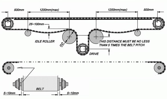
To avoid adopting auxiliary supporting bearings at the idler parts on both sides.
Minimum Diameter of Idler Roller - D ( Return Way )
Unit : mm
| Series | 100 | 200 | 300 | 400 | 500 |
| D (min.) | 180 | 150 | 180 | 60 | 150 |
Notes For Adjusting The Tension
The operating speed of the conveyor belt usually needs to match up the different conveying purpose. HONGSEBLT conveyor belt are suitable for various operating speed, please pay attention to the proportion between belt speed and the length of the catenary sag while using HONGSEBLT conveyor belt. One principal function of the catenary sag in return way is to accommodate the increase or decrease in length of the belt. It is necessary to control the length of catenary sag in a proper range, to maintain the sufficient tension of the belt after engaging with the sprockets of the drive shaft. It is very important point in overall design. For the correct dimension of the belt, please refer to Catenary Sag Table and Length Calculation in this chapter.
Tension Adjustment
As for the purpose to receive proper tension for conveyor belt. basically conveyor does no need to install with tension adjust device on the conveyor frame, it only have to increase or diminish the length of the belt, but it requiring much working time to get proper tension from it. Therefore, to install tension adjust at the drive/driven wheel of the conveyor are the easy way to receiving ideal and proper tension.
Screw Style Adjustment
For the reason to obtain the proper and an efficiency belt tension. Screw style take-ups shift the position of one of the shifts, usually the idler, through the use of adjustable machine screws. The shaft bearings are placed in horizontal slots in the conveyor frame. The screw style take-ups are used to move the shaft longitudinally, thus changing the length of the conveyor. The minimum distance between idler area must reserve at least 1.3% width of conveyor frame length, and not less than 45mm.
Notes for Low Temperature Start-Up
When HONGSBELT belt is used in low temperature condition, it must be noticed for the freezing phenomenon on the belt at start-up moment. It is because the remainder water which was remained after washing or shutting down last time, will solidify while the low temperature returns to the normal temperature and the joint position of the belt will freeze in; that will jam the conveyor system.
For prevent this phenomenon during the operation, it is necessary to start the conveyor in operating condition first, and then start the fans of freezer to dry the remainder water gradually, to keep the jointing position in active condition. This procedure can avoid the conveyor breaking because of the strong tension that is caused due to the remainder water in the jointing position of the belt has frozen.
Gravity Style Take-Up Roller
In low temperature operating condition, the supporting rails may deform due to the contraction under the extreme cold temperature, and the jointing position of the belt will freeze up, too. That will cause the conveyor belt operates with the inertion condition that differ from operating in normal temperature. Therefore, we recommend to install the gravity take-up roller on the belt in return way; it can maintain the proper tension for the belt and proper engagement for sprockets. It is not necessary to install the gravity take-up roller in the certain position; however, to install it as closed as the drive shaft will get the most effective result.
Gravity Style Take-Up
Gravity style take-up may apply in following conditions:
Temperature variations more than 25°C.
The length of conveyor frame is longer than 23M.
The length of conveyor frame is less than 15 M, and the speed is higher than 28M/min.
The speed of intermittent operation is 15M/min, and the average loading is more than 115 kg /M2 .
Example of Gravity Style Take-Up Roller
There are two methods of tension adjustment for gravity style take-up roller; one is the catenary sag type and another is the cantilever type. We recommend you to adopt the catenary sag type in low temperature environment; if the operating speed is over 28M/min, we would recommend you to adopt the cantilever type.
For the standard weight of the gravity style take-up roller, the normal temperature that is above 5°C should be 35 Kg/m and that is under 5 °C should be 45 Kg/m.
For the diameter regulations of the gravity style take-up roller, series 100 and series 300 should be over 200mm, and series 200 should be over 150mm.
Length Conveyor
FORMULA:
LS=LS1+LS1 X K
LS1=LB+L/RP X LE
LB=2L+3.1416X(PD+PI)/2
| Symbol |
Specification |
Unit |
| K | Temperature variation coefficient | mm / m |
| L | Conveyor frame length | mm |
| LB | The theoretical length of the conveyor belt | mm |
| LE | Change of the catenary sag | mm |
| LS1 | Belt length at the normal temperature | mm |
| LS | Belt length after the temperature change | mm |
| PD | Diameter of the drive sprocket | mm |
| PI | Diameter of the idler sprocket | mm |
| RP | Return way roller pitch | mm |
For LE & RP value, please refer to Catenary Sag Table in left menu.
Temperature Variation Coefficient Table - K
| Temperature Range | Length Coefficient ( K ) | ||
| P. P. | P. E. | Actel | |
| 0 ~ 20 °C | 0.003 | 0.005 | 0.002 |
| 21 ~ 40 °C | 0.005 | 0.01 | 0.003 |
| 41 ~ 60 °C | 0.008 | 0.014 | 0.005 |
Value Explanation
Example 1:
The length of conveyor frame is 9000mm; adopting Series 100BFE which width is 800mm, spacing of the return way roller is 950mm, the drive/idler sprockets are selected to adopt series SPK12FC which diameter is 192mm, running speed is 15m/min, and the range of operating temperature are from -20°C to 20°C. The result of calculation for installing measurement is as follows:
LB=2×9000+3.1416×(192+192)/2=18603(mm)
LS1=18603+9000/900×14=18743
LS=18743+(18743×0.01)=18930 ( Dimension increases when contraction )
The result of calculation is 18930mm for actual installation
Example 2:
The length of conveyor frame is 7500mm; adopting Series 100AFP which width is 600mm, spacing of the return way roller is 950mm, the drive/idler sprockets are selected to adopt SPK8FC which diameter is 128mm, running speed 20M/min, and the range of operating temperature are from 20°C to 65°C. The result of calculation for installing measurement is as follows:
LB=2×7500+3.1416×(128+128)/2=15402(mm)
LS1=15402+7500/900×14=15519
LS=15519-( 15519 × 0.008 )=15395 ( reduce the belt length when hot expansion )
The result of calculation is 15395mm for actual installation.
Table of Catenary Sag
| Length of The Conveyor | Speed (m/min) | RP ( mm ) | Maximum SAG (mm) | Ambient Temperature (°C) | ||||
| Sag | LE | P.P. | P.E. | ACTEL | ||||
| 2 ~ 4 m | 1 ~ 5 | 1350 | ± 25 | 150 | 30 | 1 ~ 100 | - 60 ~ 70 | - 40 ~ 90 |
| 5 ~ 10 | 1200 | 125 | 30 | 1 ~ 100 | - 60 ~ 70 | - 40 ~ 90 | ||
| 10 ~ 20 | 1000 | 100 | 20 | 1 ~ 90 | - 50 ~ 60 | - 20 ~ 90 | ||
| 20 ~ 30 | 800 | 50 | 7 | 1 ~ 90 | - 20 ~ 30 | - 10 ~ 70 | ||
| 30 ~ 40 | 700 | 25 | 2 | 1 ~ 70 | 1 ~ 70 | 1 ~ 90 | ||
| 4 ~ 10 m | 1 ~ 5 | 1200 | 150 | 44 | 1 ~ 100 | - 60 ~ 70 | - 40 ~ 90 | |
| 5 ~ 10 | 1150 | 120 | 28 | 1 ~ 100 | - 60 ~ 60 | - 30 ~ 70 | ||
| 10 ~ 20 | 950 | 80 | 14 | 1 ~ 85 | - 40 ~ 40 | - 10 ~ 50 | ||
| 20 ~ 30 | 800 | 60 | 9 | 1 ~ 65 | - 10 ~ 30 | 1 ~ 80 | ||
| 30 ~ 40 | 650 | 25 | 2 | 1 ~ 40 | 1 ~ 60 | 1 ~ 80 | ||
| 10 ~ 18 m | 1 ~ 5 | 1000 | 150 | 44 | 1 ~ 100 | - 50 ~ 60 | - 40 ~ 90 | |
| 5 ~ 10 | 950 | 120 | 38 | 1 ~ 100 | - 50 ~ 50 | - 40 ~ 90 | ||
| 10 ~ 20 | 900 | 100 | 22 | 1 ~ 90 | - 40 ~ 40 | - 35 ~ 80 | ||
| 20 ~ 30 | 750 | 50 | 6 | 1 ~ 80 | - 10 ~ 30 | - 35 ~ 80 | ||
| 30 ~ 35 | 650 | 35 | 4 | 1 ~ 70 | - 5 ~ 30 | - 10 ~ 80 | ||
| 35 ~ 40 | 600 | 25 | 2 | 1 ~ 65 | 1 ~ 60 | 0 ~ 80 | ||
| 18 ~ 25 m | 1 ~ 5 | 1350 | 130 | 22 | 1 ~ 100 | - 60 ~ 60 | - 40 ~ 90 | |
| 5 ~ 10 | 1150 | 120 | 28 | 1 ~ 95 | - 50 ~ 50 | - 40 ~ 85 | ||
| 10 ~ 15 | 1000 | 100 | 20 | 1 ~ 95 | - 40 ~ 40 | - 30 ~ 80 | ||
| 15 ~ 20 | 850 | 85 | 16 | 1 ~ 85 | - 30 ~ 40 | - 30 ~ 80 | ||
| 20 ~ 25 | 750 | 35 | 3 | 1 ~ 80 | 1 ~ 60 | 0 ~ 70 | ||
When speed is over 20m/min, we recommend adopting ball bearings to support the belt in the return way.
No matter what speed designs, the drive motor should adopt the speed reduction device, and start-up in low speed condition.
We recommend value RP as the best distance. The spacing in actual design should be less than value RP. For the spacing between return way rollers, you can refer to the table above.
Value SAG is an ideal maximum; the elasticity of the belt should be controlled within the range of value SAG.
Value LE is an increasing length of the sag after subtracting the belt length in theory.